|
|
 |
|
|
|
| |
|
| |
|
|
| |
1. Features |
|
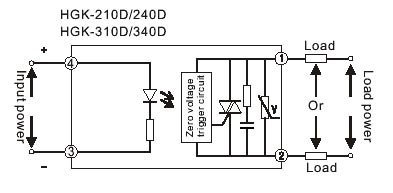
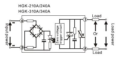
TRIAC output, Zero current turn-off
INput and output 4000V optically isolated
LED indicator
INternal RC snubber
Internal varistor (MOV) and RC snubber dual surge absorb protect
Zero voltage and random turn-on switching
100% tested at rated current , CE compliant
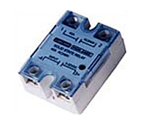
With safety cover, panel mount |
| |
|
2. Application
|
| |
HGK Series AC Solid State Relays, adapting ignition-proof engineering plastic cover,unique sculpt, origina l architecture, screw thread connection, have the features of hard structure, vibration-proof capability high , input current small convenient to interface with terminals of computer and various digital tele-control circuit . This series are widely used in the fields of petrochemical equipment, foodstuff producing mechanism , packaging machines, textile and plastic mechanisms, tool numerical control, gymnasium equip . Speciality be the same with canker, aquosity request prevent explode scurvines circumstance, and ofte n switch of occasion . |
| |
| |
|
3. Precautions |
| |
-
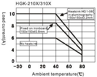
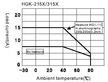
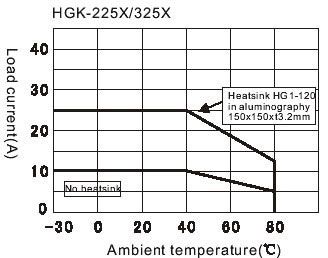
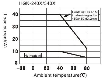
Heatsink should be used when the current is up to 5 Amperes, and heat-conductive silicate should be spreaded between the heatsink and the base.
-
When controlling inductive load, the SSR may be damaged by the high transient voltage and surge current added on the output, so some special clamping devices to control voltage, such as zener diode, varistor(MOV).
-
When controlling a small current(close to Min. Load current), a dummy load resistance should b e parallelled to reduce the rest higher voltage produced by the leakage current on the outpu t
-
To avoid the temperature exceeding the allowance, heatsink efficiency and the mounting positio n should be regarded, suitable space will be left when two or more SSR are mounted .
-
The output end must not be used in parallel to enlarge the current, however can be used in series for higher suitable operating voltage.
-
The input end can be used either mean when sharing a control power supply.
-
Please contact HALON application engineering department for additional information and specific
application questions.
|
Iutput parameters (TA:25℃) : |
| |
Input type |
D:DC Control |
A:AC Control |
Control voltage range |
3-32 VDC |
90-280 Vrms (50-60Hz) |
Turn-on voltage(Max.) |
3.0 VDC |
90 Vrms |
Turn-off voltage(Min.) |
1.0 VDC |
10 Vrms |
Nominal input impedance |
1500 Ohms |
60 Ohms |
Typical input current |
10mA@5 VDC 22mA@ 24 VDC |
5mA@220 VAC 2.2mA@110 VAC |
Max.Reverse voltage |
-32 VDC |
_ |
|
| |
| |
4. Teahnical Data |
| |
Output current type |
10 |
15 |
25 |
40 |
Operating voltage range |
2:28 280VAC 3:48 480VAC |
Max. Load current |
10A |
15A |
25A |
40A |
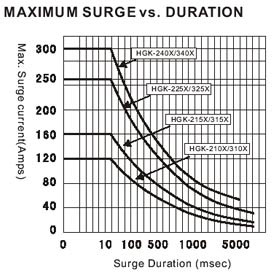
Max. Surge current-Non repetitive (10ms) |
120Apk |
160Apk |
250Apk |
300Apk |
2Max. I t for fusing(10ms) |
272A s |
128 2As |
312 5 sA2 |
450 2As |
Thermal resistance junction to case(Rjc) |
2.5 ℃/W |
2.3℃ /W |
1.1 ℃/W |
0.9℃ /W |
Min. Off-state dv/dt |
250V/usec |
500V/usec |
250V/usec |
250V/usec |
Max. Over-zero voltage |
35VAC |
Min. Load current |
100mA |
Max. On-state voltage drop |
1.5VAC@rated current |
Max. Off-state leakage current |
5mA,1mA /no RC @rated voltage |
Transient over voltage |
2:800Vpk 3:1000Vpk |
Operating frequency range |
47 63Hz |
Dielectric strength 50Hz 1Min( ) |
4000VAC input-output 2500VAC input/output-base |
Insulation resistance |
1000MQ 500VDC Voltage Test |
Vibration resistance Destructive Functional |
117.6mm/s2(12G),10-55 Hz double Amplitude of 2 mm 117.6mm/s2(12G),10-55 Hz double Amplitude of 2 mm |
Destructive FunctionalShock resistance |
Min.980m/s2(100G)(5 times each for X,Y,Z axis) Min.980m/s2(100G)(4 times each for X,Y,Z axis) |
Max. Capacitance |
8pF (input-output ) |
Max. Turn-on time |
Zero voltage turn-on |
(1/2 cycle of load power)+1msec(DC input) (3/2 cycle of load power)+1msec(AC input) |
Random turn-on |
1msec |
Max. Turn-off time |
(1/2 cycle of load power)+1msec(DC input) (3/2 cycle of load power)+1msec(AC input) |
Ambient operating temperature |
-30℃ to 80℃ |
Ambient storage temperature |
-30℃ to 120 ℃ |
Ambient humidity relative |
45% to 85% |
Weight typical |
≤85g |
|
| |
| |
5. Connection / Wiring |
|
|
| |
|
| |
|
| |
|
| |
|
| |
|
| |
|
| |
|
| |
| |
| |
|
|